Showing posts with label Architecture. Show all posts

Jul 23, 2015

Cisco - UCS Mini - Architecture

Useful Link


Cisco UCS Mini Solution Components
  • Cisco UCS Mini supports a wide variety of Cisco UCS B-Series Blade Servers. All supported servers can be mixed and matched to customize a Cisco UCS Mini solution for your specific needs and applications.
Cisco UCS B200 M4 Blade Server
  • Delivering enterprise-class performance in a compact form factor, the Cisco UCS B200 M4 Blade Server can quickly deploy stateless physical and virtual workloads. The server addresses a broad set of workloads, including IT and web infrastructure and distributed database, enterprise resource planning (ERP), and customer relationship management (CRM) applications. The Cisco UCS B200 M4 is built on the Intel® Xeon® processor E5-2600 v3 processor family, with up to 768 GB of memory, up to two hot-pluggable drives, and up to 80-Gbps total bandwidth. It offers exceptional levels of performance, flexibility, and I/O throughput to run the most demanding applications.
Cisco UCS B200 M3 Blade Server
  • Delivering performance, versatility, and density without compromise, the Cisco UCS B200 M3 Blade Server is designed for customers who do not need the features and performance of the latest Intel Xeon processors but who still need a versatile workhorse server. The Cisco UCS B200 M3 server harnesses the power of the Intel Xeon processor E5-2600 v2 product family, with up to 768 GB of RAM, two hot-pluggable hard drives, and 10 Gigabit Ethernet connectivity.
Cisco UCS B420 M3 Blade Server
  • Designed for enterprise performance and scalability, the Cisco UCS B420 M3 Blade Server combines the advantages of 4-socket computing with the cost-effective Intel Xeon processor E5-4600 and E5-4600 v2 product families for demanding virtualization and database workloads. It offers industry-leading computing density, I/O bandwidth, and memory footprint. The full-width Cisco UCS B420 M3 supports 1.5 terabytes (TB) of memory and takes full advantage Cisco UCS virtual interface card (VIC) technology for up to 160-Gbps aggregate I/O bandwidth.
Cisco UCS B22 M3 Blade Server
  • The Cisco UCS B22 M3 Blade Server delivers a balanced price-to-performance ratio feature set to address quick deployment of IT infrastructure and scale-out workloads. The Cisco UCS B22 M3 server takes advantage of the power of the Intel Xeon processor E5-2400 product family, with expandability to 384 GB of RAM, two hot-pluggable hard drives, and 10 Gigabit Ethernet connectivity.

Cisco UCS 5108 Blade Server Chassis
  • The Cisco UCS 5108 Blade Server Chassis for the Cisco UCS Mini can accommodate up to eight half-width or four full-width Cisco UCS blade servers. The 6-rack-unit (6RU) chassis can be mounted in an industry-standard 19-inch rack such as the Cisco® R Series Racks or be placed on any sturdy surface2. Dual-voltage AC (100 to 120V3 and 200 to 240V) power supplies make Cisco UCS Mini ready for global deployment.


Cisco UCS 6324 Fabric Interconnect

  • The Cisco UCS 6324 Fabric Interconnect extends the Cisco UCS architecture into environments that require smaller domains. Providing the same unified server and networking capabilities as the top-of-rack Cisco UCS 6200 Series Fabric Interconnects, the Cisco UCS 6324 Fabric Interconnect embeds the connectivity within the Cisco UCS 5108 Blade Server Chassis to provide a smaller domain of up to 15 servers: 8 blade servers and up to 7 direct-connect rack servers. Figure 1 shows a Cisco UCS Mini solution with optional rack servers.


Cisco UCS Manager
  • Cisco UCS Manager provides unified, embedded management of all software and hardware components in a Cisco UCS Mini solution. It offers an intuitive GUI, a command-line interface (CLI), and a robust API to manage all system configuration and operations.
  • Starting with Cisco UCS Manager Release 3.0(2), a new HTML 5 user interface is available, eliminating the need for Java4 for console access.
  • Optional components include Cisco UCS C-Series Rack Servers and Cisco UCS Central Software for managing multiple instances of Cisco UCS Mini.

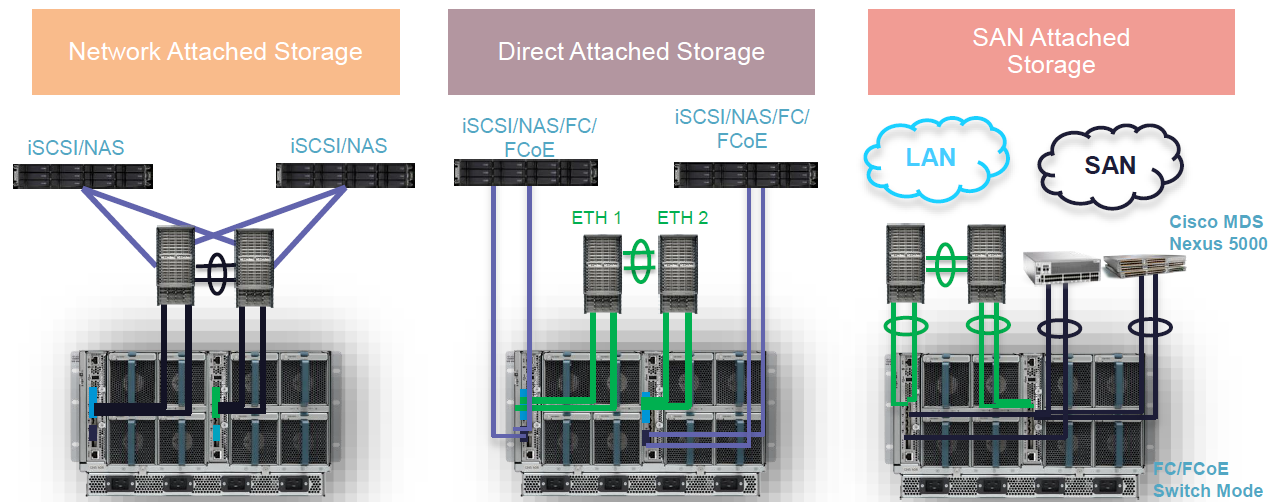
Storage Architectural Support


  • •FC switching mode only, no NPV mode for first release
  • •Both native FC/FCOE supported
  • •FCoEsupport both local attach and remote target (VF/VE)
    • –FC support both local attach and remote target (TF/TE)
    • –FCoEport-channel and FC san-port-channel supported
    • •VFC over ETH (uplink port/storage port only)
  • •VFC over VETH (blade vfcports)
  • •Uplink ports (1/1-4)can be fcoeuplink/fcoestorage/FC (switch mode)
  • •Scalability ports (1/5/1-4) can be fcoestorage only

Apr 8, 2015

EMC - DataDomain - Hardware Overview

1. Overview
Data Domain systems are
based around the same basic hardware architecture. Documents for each hardware model are published on the Data Domain support site. Hardware features common to all models include: rack mountable in four-post racks; hot-swappable disks with redundant hot-swappable fans and redundant hot-swappable power modules; serial port and copper Ethernet ports; DIMM modules for RAM; a battery backed NVRAM card; video, keyboard, and mouse ports to connect to a monitor and keyboard and mouse; front panel LEDs that provide system status indicators.


Components under high mechanical or electrical stress such as spinning drives, fans, and power supplies are provided with N+1 redundant configuration, N+1 redundancy is a system configuration in which certain components have at least one independent backup component to ensure system functionality continues if a part fails. This allows for uninterrupted operation at full capacity and operational status if one component fails. For data, RAID 6 technology provides additional protection of data integrity when up to two disks fail

Data Domain systems may be connected to Ethernet networks for TCP/IP-based data transfer and system management. All models have two built-in ports. Some models may be configured with additional ports by adding optional Ethernet expansion cards. Newer systems also include a dedicated Ethernet port for what is known as lights out management or remote system management. Interface cards are usually added to provide additional network capacity.


Connecting to a Fibre Channel-based storage area network is supported by adding a host bus adapter card. In these environments the virtual tape library VTL software license is also required


For repairs in the field, access to the command line interface to shut down restart and run diagnostics is usually through the serial port. The username for the built-in administrator is sysadmin.


The DD990 and older models provide keyboard and PS2 mouse port for connecting directly to the unit with a keyboard and monitor. Check with the onsite administrator for the preferred access method


The majority of Data Domain system models support the expansion of storage with the addition of expansion shelves. There are three different generations of expansion shelves to consider. These three models are still active in existing and new systems: the ES20, the first generation of the ES30 with SATA drives, and a second generation ES30 with SAS drives. The two different ES30 drive types cannot be mixed in a shelf.
The two different ES30 drives are distinguished only with drive labels. Note that the ES30 SATA shelf label can indicate up to 2 TB, while the ES30 SAS shelf label can indicate up to 3 TB

The 3U Data Domain ES20 expansion shelf has 16 disks for increased storage capacity of certain
models. The expansion shelf fits in a standard 19-inch rack and connects to either a Data Domain
system or to another expansion shelf.


2. Rack Components
Overview
  • EMC Titan 40U Rack with DD branding
  • Preconfigured DD990 in rack
  • ES30 preconfigured option for DD7200 and several mid‐range controllers (controller will ship separately)
  • Empty Rack optio Shelves
  • ES30 Expansion Shelves will be an option to be pre‐installed at the factory in the Data Domain Rack
    • Maximum 12 ES30s per rack
    • Rack
  • Selectable power cords (standard to EMC)
  • Optional rack stabilizer (standard to EMC)


Here are the physical specifications for the Data Domain Rack. Take a minute to review
before proceeding.
  •  40 RU / 2 Meters tall
  •  24 inches Wide X 39 inches Deep X 75 inches Tall
  •  NEMA 19‐inch standard equipment mounting
  •  EIA‐310D round mounting holes
  •  Weight
    •  Empty Rack ~ 380 lbs (173 Kg)
    •  Maximum device ~ 2,100 lbs (953 kg)
  •  Branded Console Panel
  •  Filler Panels
  •  Rear Door
  •  Removable Side and Top Panels
  •  Casters (front are fixed, rear swivel)
  •  Dual 4.8 kVA redundant AC power distribution

3. Products Line

DD990
Key differences between the DD990 and a DD990 with DD Extended Retention software
option configuration are highlighted in bold. Take a minute to review before proceeding.
  •  Quad‐socket, 10‐core Xeon processors (Westmere‐EX)
  •  Two memory configurations available
    •  Base: 128 GB supports up to 360 TB raw, 285 TB usable
    •  Expanded: 256 GB supports up to 720 TB raw, 570 TB usable
  •  External expansion using ES30 and ES20 shelves
    •  Three quad‐port 6 Gb/s SAS HBAs for external connectivity
    •  Connectivity up to 24 shelves, or up to max capacity
  •  Four I/O slots for data access connectivity
    •  Up to four dual‐port 1 GbE NICs, optical
    •  Up to four quad‐port 1 GbE NICs, copper
    •  Up to three dual‐port 10 GbE NICs, copper with SFP+ interface
    •  Up to three dual‐port 10 GbE NICs, optical with LC interface
    •  Up to three dual‐port 8 Gb Fibre Channel VTL HBAs
    •  Simultaneous usage of NIC and VTL cards
  •  Two 2 GB remote‐battery NVRAM with Battery Backup Unit


DD7200

The DD7200 enables users to backup 208 TB in under 8 hours with up to 26 TB/hr aggregate ingest performance with DD Boost. The base of this scalable system supports up to 18 expansion shelves of 2 TB or up to 12 expansion shelves of 3 TB, which enables customers to protect up to 21.4 PB logical and 428 TB usable capacity in a single namespace – this includes support for both 2TB and the new 3TB ES30 expansion shelves with these conditions:
  • New orders ‐ Factory ships only ES30 SAS Shelves, with 2TB or 3TB HDDs
    • DD7200 also supports legacy ES20 and ES30 SATA Shelves
    • SAS and SATA shelves cannot be mixed on the same set
With the Data Domain Extended Retention software option, this scalable system can support up to 56 expansion shelves, which enables customers to protect up to 85.6 PB logical and 1.7 PB usable capacity for long-term backup retention. In addition, the DD7200 can be the target for up to 540 backup streams, enabling consolidation from up to remote sites or the ability to emulate up to virtual tape drives on a single system.


DD2500
The DD2500 enables users to backup 175 TB in under 8 hours with up to 13.4 TB/hr aggregate ingest performance with DD Boost. The DD2500 has two capacity configurations:
  • 7 x 3 TB HDDs, ~11.2 TB usable
  • 12 x 3 TB HDDs, ~25.9 TB usable


Apr 6, 2015

EMC Avamar - Architecture

1. Overview
EMC Avamar is a comprehensive, client-server network backup and restore solution. With its unique global data deduplication technology, Avamar addresses the data protection challenges in today’s IT environments.
  • The ever-increasing amount of data to backup presents a challenge to organizations facing the demands of shorter backup windows, quicker restore responses, consistent backups of remote sites, and regulatory requirements; all with the need to accomplish this with fewer staff and tighter budgets.
  • Avamar meets these challenges by re-designing backup and restore as true disk-based processes. Avamar’s patented global deduplication technology reduces the amount of backup data by identifying unique data at the source. Avamar stores only one copy of this common data across the backup network. This results in a dramatic reduction in the amount of data that is moved across the network and stored in backup storage. The same data is backed up as in traditional backup systems, but consumes significantly less network and backup resources as only unique data is stored. And, by using standard IP network technologies, dedicated backup networks are not required.
  • Avamar employs a scalable disk-based, server architecture built of modules that provide a balance of connectivity, security, processing and disk storage resources. Scheduled backup and replication functionality enable efficient backup of remote sites and provide disaster recovery of primary backup sites. Avamar provides a user-friendly interface for central management of the entire backup system.


Tradional Backup

A high percentage of data that is retained on backup media by most backup solutions is highly redundant. The typical backup process for most organizations consists of a series of daily incremental backups and weekly full backups.

  • Daily backups are usually retained for a few weeks and weekly full backups are retained for several months to several years. Because of this process, multiple copies of identical or slowly-changing data are retained on backup media, leading to a high level of data redundancy.
  • A large number of operating systems, application files and data files are common across multiple systems in an enterprise. Identical files such as Word documents, PowerPoint presentations and Excel spreadsheets, are stored by many users across an environment. Backups of these systems contain a large number of identical files.
  • Additionally, many users keep multiple versions of files that they are currently working on. Many of these files differ only slightly from other versions, but are seen by backup applications as new data that must be protected.
  • Backing up redundant data increases the amount of backup storage needed and can negatively impact network bandwidth. Organizations are running out of backup window time and facing difficulties meeting recovery objectives due to the need to manage backup versions and a myriad of backup tapes.


Avamar Advantage
Avamar differs from traditional backup and restore solutions by identifying and storing only unique, sub-file data objects. Redundant data is identified at the source, drastically reducing the amount of backup data that travels across the network to be stored and managed by the backup host. When storing data objects, Avamar takes maximum advantage of inherent hard-disk characteristics. Avamar also creates and stores “trees” that link all data objects from a single backup. These “trees” are used to re-create files for restore.


2. Features
  • Global data deduplication ensures that data objects are only backed up once across the backup environment.
  • Systematic fault tolerance, using RAID, RAIN, checkpoints and replication, provides data integrity and disaster recovery protection
  • Highly reliable, inexpensive disk storage is used for primary backup storage.
  • Since standard IP network technologies optimize the use of the network for backup, dedicated backup networks are not required. Daily full backups are possible using existing networks and infrastructure.
  • Scalable server architecture provides security and expandability. Additional storage nodes can be added to an Avamar multi-node server to accommodate increased backup storage requirements.
  • Flexible deployment options include Avamar Virtual Edition and Avamar Data Store. Avamar supports a wide-variety of client operating systems and applications, including: Windows, Linux, Unix, NDMP, Microsoft SQL, Microsoft Exchange, SharePoint, and Oracle. With its global deduplication technology, Avamar is an efficient backup choice for VMware and remote office backup environments.
  • Centralized management is also provided. Avamar Enterprise Manager and Avamar Administrator interfaces enable remote management and monitoring of Avamar servers from a centralized location via internet access. Avamar can also integrate with Data Protection Advisor and Backup & Recovery Manager for further monitoring capabilities.


Terminology


  • An object is a single instance of deduplicated data. Objects are stored and managed within stripes on the Avamar server. An object is also sometimes referred to as a chunk.
  • A stripe is a unit of disk drive space managed by Avamar. Objects are stored within data stripes.
  • A node is a self-contained, rack-mountable network-addressable computer consisting of both processing power and hard drive storage. Nodes run Avamar server software on the Linux operating system.
  • A server is a group of one or more nodes on a local, high-speed network.
  • A system is one or more Avamar servers and the servers or desktop clients that back up data to those Avamar servers.


Avamar COmponents


  • The Avamar Server stores client backups and provides essential processes and services required for client access and remote system administration. Avamar Administrator Server (mcs) and Avamar Data Server (gsan) run on the Avamar server.
  • Avamar Client software runs on each computer or network server that is being backed up. Avamar provides client software for various computing platforms. Each client consists of a client agent and one or more plug-ins.
  • Avamar Administrator is a user management console software application that is used to remotely administer an Avamar system from a supported Windows or Linux computer


Avamar Server Node Types


  • Utility nodes are dedicated to providing internal Avamar server processes and services, including the administrator server, external authentication, Network Time Protocol (NTP), and web access. 
  • Storage nodes include the Avamar Data Server software and are dedicated to providing backup storage. 
  • The NDMP Accelerator is an optional specialized node that, when used as part of an Avamar system, provides a complete backup and recovery solution for NAS devices via the Network Data Management Protocol (NDMP). Avamar supports EMC Isilon, VNX, and Celerra and NetApp filers with the NDMP Accelerator. 
  • The Media Access Node is an optional node that can be used as a pass-through device for sending Avamar backup data to tape for long term storage


Systematic Fault Tolerance


  • RAID (redundant array of independent disks) is a method of protection for disk data corruption. RAID is a balance between performance and efficiency. Avamar servers are protected by either RAID-1 or RAID-6, depending on the configuration. Avamar also has hot-swap capability with minimum system impact for highest failure-rate components (more than 90% of expected failures). 
  • RAIN (redundant array of independent nodes) provides failover and fault tolerance across nodes. RAIN provides uninterrupted functionality during node failure, replacement and reconstruction. In the unlikely event of a node failure, the backup data will be stored on the remaining nodes; data for recoveries is reconstructed using parity. RAIN is used to replace the failed node, reconstruct the data on the replacement node, and when expanding an Avamar server, rebalance the capacity across all nodes. 
  • Replication protects against data loss in the event of a server loss. Efficient, scheduled replication (local or remote) ensures availability/redundancy of data if primary server is lost. 
  • Checkpoints protect the server in the event of operational failures. They provide redundancy across time. Checkpoints are a read-only snapshot of the Avamar server taken to facilitate server rollbacks. They are created using hard-links to all the stripes. Regular checkpoint validation, including auto-repair capability, is used to ensure data integrity. 
  • High Availability Uplink and Dual Switches provide high availability in the event of hardware failure. 

Jan 23, 2015

EMC - iSilon - Architecture

1. EMC Isilon Scale-out Storage Platform architecture
The EMC Isilon Storage Platform consists of a number of storage nodes that provide storage and network connectivity for the cluster, an internal Infiniband network and external networking connectivity that provides access to clients.
  • EMC Isilon operates as a scalable appliance behind a customer’s Ethernet infrastructure.
  • EMC Isilon uses standard 10 gigabit and one gigabit Ethernet and speaks industry standard protocols to provide a high level of compatibility with existing and new infrastructures.


1.1 Interconnect
The Cluster interconnect is InfiniBand, which was designed as a high-speed interconnect for high performance computing. The architecture can run on any suitably fast technology, InfiniBand just presents the best performance characteristics today.
The interconnect is very important to OneFS. It carries block I/O and internal message passing, so it needs to be both high throughput and very low latency. We are usually shipping the fastest standard that’s in mass production, and InfiniBand has never been a bottleneck.
A single front-end operation like a chmod can generate multiple messages on the back-end. There’s more to it than this, and frequently the lock will be cached. But the main point is that the reliability and performance of the interconnect is very important to creating a high-performance, true scale-out storage system.

1.2 External Network
The external networking components of an EMC Isilon cluster provide client access over a variety of protocols, including NFS, SMB, HDFS (Hadoop File System), FTP and HTTP. Each storage node connects to one or more external Ethernet networks using 1 or 10 Gigabit connections, or a combination of both. Each node supports either four (4) 1 Gigabit Ethernet connections, or two (2) 1 Gigabit and two (2) 10 Gigabit Ethernet connections. 1 Gigabit ports use standard RJ45 connectors and category 5e or 6 cables, while 10 Gigabit ports use either SFP+ optical or copper transceivers

1.3 Protection & Availability

  • OneFS supports very flexible data protection methods as granularly as an individual file or folder.
  • Data can be mirrored from two ways up to eight ways.
  • For data protection with lower overhead Forward Error Correction or FEC is used to distribute data in a way that is statistically likely to provide fault tolerance.
  • These data protection policies can be changed at any time and the data will be re-protected at its new level in the background.
  • FEC can support from one up to four simultaneous failures without losing access to data.
  • The nomenclature used here is N+M where N is the number of nodes containing data and M is the number of nodes or node components that can fail simultaneously.
  • Minimum cluster sizes are required to support higher p
    rotection levels since quorum should be preserved in the event of tolerable simultaneous component failure.
In addition to supporting the N+M configuration, EMC Isilon supports an N+M:B option as well. As was stated earlier, M represents the number of drives or nodes that can fail and not impact data availability. Because the likelihood of a node failure is significantly lower than that of a drive failure, the :B option allows the administrator to override the node failure value of the protection level. So, in a 4+2:1 configuration, the system can tolerate two drive failures or 1 node failure. While this may not seem like a good option at first, it does provide a significant amount of capacity savings by reducing the amount of protection information that is stored on the system.
EMC Isilon supports protection levels of N+2:1 and N+3:1 in addition to the options previously discussed.

2. Where the EMC Isilon solution may not be a good fit
  • Applications that have high single-stream I/O requirements cannot take advantage of the EMC Isilon cluster’s distributed model, and will generally perform better on a traditional scale-up system, such as the VNX. Also, small, random I/O is not optimal for the EMC Isilon. Small random reads do not benefit from the aggressive pre-fetching capabilities of the EMC Isilon cluster, and small random writes do not utilize the write coalescing capabilities.
  • Transactional applications, such as Oracle, SAP, SQL, Exchange and SharePoint, have I/O profiles that are not a good fit – single stream or small, random reads and writes.
  • Finally, Tier 1 & 2 virtualized applications also often have non-optimal I/O profiles. This includes VDI/end-user computing solutions.

3. Documents


Isilon Student Guide Foundations
Useful Link


Jan 22, 2015

Cisco - UCS - Architecture

1. Introducing the Cisco Unified Computing System
The Cisco Unified Computing System is a next-generation data center platform that unites compute, network, storage access, and virtualization into a cohesive system designed to reduce total cost of ownership (TCO) and increase business agility. The system integrates a low-latency, lossless 10 Gigabit Ethernet unified network fabric with enterprise-class, x86-architecture servers. The system is an integrated, scalable, multichassis platform in which all resources participate in a unified management domain. The main system components include:
  • UCS System and Connectivity View
    • Single Management Interface for up to 160 blade servers
    • Role Based Access for LAN, SAN, and Server Administrators
    • Clustered for fault tolerance and no single point of failure for any chassis
    • Open APIs for third party integration
  • Unified Computing System Manager
    • Embedded device manager for family of UCS components
    • Enables stateless computing via Service Profiles
    • Efficient scale: Same effort for 1 to N blades
    • APIs for integration with new and existing data centre infrastructure
  • Single point of management for UCS system of components
    • Adapters, blades, chassis, fabric extenders, fabric interconnects
  • Embedded device manager
    • Discovery, Inventory, Configuration, Monitoring, Diagnostics, Statistics Collection
    • Coordinated deployment to managed endpoints
  • APIs for integration with new and existing data centre infrastructure
    • SMASH-CLP, IPMI, SNMP
    • XML-based SDK for commercial & custom implementations
 2. UCS Technical System Architecture
What is a “stateless” computing architecture?
  • Stateless client computing is where every compute node has no inherent state pertaining to the services it may host.
  • In this respect, a compute node is just an execution engine for any application (CPU, memory, and disk – flash or hard drive).
  • The core concept of a stateless computing environment is to separate state of a server that is built to host an application, from the hardware it can reside on.
  • The servers can easily then be deployed, cloned, grown, shrunk, de-activated, archived, re-activated, etc
UCS Service Profiles
  • Servers are specifically purchased for additional capacity and provide service elasticity
  • Server identities are defined by the service profile
  • Management of servers provided through the very system that defines them (UCSM).

3. Documents
UCS Management Deep Dive

Architecture of the Cisco UCS

Cisco UCS Administration and RBAC

Multi-UCS Management with UCS Central

UCS Networking Deep Dive