Nov 13, 2015

EMC Federation Enterprise Hybrid Cloud 3.1 Disaster Recovery

.


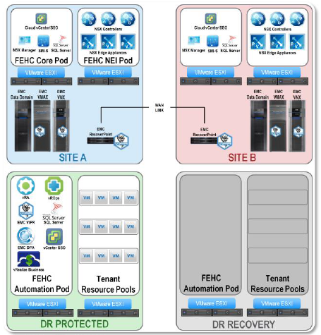
In the Federation Enterprise Hybrid Cloud v3.0, the foundation architecture has been changed to match the disaster recovery (DR) architecture from v2.5.1


Specifically, this means that an additional SSO and SQL server are deployed in the Automation Pod, allowing the other components in the Automation pod to fail over and still have access to those services.
This change allows customers to add DR functionality at a later time without having to make any architectural changes to the underlying infrastructure.


Protected sites can now be used as recovery sites as well, allowing for either site to fail while retaining the ability to provision new resources.
In this example, the site in Phoenix serves as the recovery site for Boston, and vice versa. If the Boston site were to experience a failure, the Boston resources could be activated in Phoenix as part of the disaster recovery protocol.
If the Boston site remained down for an extended amount of time, new resources that are intended to be run in Boston could be provisioned at the Phoenix recovery site in the interim.
When the Boston site comes back online, the newly created resources could then be replicated to Boston and set as “protected” as if they had been originally created there. While all of this is taking place, operations in Phoenix are unaffected.


In the Federation Enterprise Hybrid Cloud v3.0, a new Catalog Item was created that allows us to pair clusters from within vRealize Automation. This workflow allows us to set the properties and key values that are necessary for the cluster to function within a DR environment.
This was done manually before. Now, it is automated in a workflow/catalog item.
Once the cluster pair is created, it is still required to manually create the recovery plan in SRM based on the cluster name and properties.

.
.
..

Nov 12, 2015

EMC Cloud Tiering Appliance Fundamentals CTA Hardware Overview


CTA’s most recent platform model is the Generation 8, which is built on the Intel 1U 2-socket rack-mounted server. This platform uses a Dual Intel Sandy Bridge 2.0 GHz processor. It contains 16 GB of RAM and four 900 GB SAS drives configured in a RAID 5 with one hot spare.
For network interface ports, the server comes with four gigabit Ethernet ports on the motherboard. There is also an available IO module providing an additional 2-ports for 10GbE.


Another platform option for the CTA is the Generation 7 (Gen-7) model. This model is a Dell R710 2U server with only 4 GB of RAM instead of the Gen-8’s 16 GB.
The Gen-7 comes with four 1 TB SATA drives in a RAID 1 configuration with two hot spares. There are two gigabit Ethernet ports for network connection. With this model, only 250 million files can be archived per appliance.


The oldest CTA hardware model is the Generation 6 (Gen-6). The Gen-6 is built on the Dell 2950 server. This model contains a Dual Intel 3.0 GHz Xeon processor with 4 GB of RAM.
There are four 250 GB SATA drives in a RAID 5 configuration with one hot spare. As with the Gen-7 model, the Gen-6 only has two gigabit Ethernet ports for networking and has a limitation of 250 million archived files per appliance


In the event that a Gen-8 CTA or CTA-HA becomes unresponsive, a network console management page is available to allow users to control the appliance or reboot the system.
The console can be accessed through a dedicated management port on the back of the appliance which is labeled MGMT. For security purposes, network console management should be enabled on a network with access limited to system administrators only.

The requirements to implement a CTA/VE solution are four virtual CPUs, 16 GB of virtual RAM, 1 TB of virtual disk space and two Gigabit virtual interfaces must be reserved. For a CTA/VE-HA, the only differences compared to a CTA/VE is that only 4 GB of virtual RAM is needed along with 100 GB of virtual disk space. Both CTA/VE and CTA/VE-HA support ESXi server 4.1 and later, as well as ESX server 4.0 and later.
Disk space for the CTA/VE can be thin provisioned from the backend. Make sure that 1 TB is available in case the CTA/VE will need to archive close to its limit of 500 million files.


For many environments, using a single CTA or CTA/VE network interface will satisfy networking requirements. However, there are cases when more complex topologies are used.
The CTA supports combining Ethernet interfaces to form a bonded interface. This topology is used for high availability, to protect the CTA installation from a single point of failure. You may also use two subnets or more, one for the primary storage tier, and another for either the secondary tier or for a management interface. One port can be used for one subnet, and another port for the second subnet. The CTA also supports VLAN tagging and VLAN bonding, which is a VLAN interface created on top of a bond interface. Be aware that bonding or VLAN bonding is not supported on the CTA/VE.

EMC VPLEX Management Overview


VPLEX provides two methods of management through the VPLEX Management Console. The
Management Console can be accessed through a command line interface (CLI) as well as a
graphical user interface (GUI). The CLI is accessed by connecting with SSH to the Management
Server and then entering the command vplexcli. This command causes the CLI to telnet to port
49500.
The GUI is accessed by pointing a browser at the Management Server IP using the https protocol.
The GUI is based on Flash and requires the client to have Adobe Flash installed.
Every time the Management Console is launched, it creates a session log in the /var/log/VPlex/cli/
directory. The log is created when launching the CLI as well as the GUI. This can be helpful in
determining which commands were run while a user was using VPLEX.


EMC VPLEX software architecture is object-oriented, with various types of objects defined with
specific attributes for each. The fundamental philosophy of the management infrastructure is
based on the idea of viewing, and potentially modifying, attributes of an object.


The VPLEX CLI is based on a tree structure similar to the structure of a Linux file system.
Fundamental to the VPLEX CLI, is the notion of “object context”, which is determined by the
current location or pwd within the directory tree of managed objects.
Many VPLEX CLI operations can be performed from the current context. However, some
commands may require the user to cd to a different directory before running the command

Useful Link

 VPLEX Architecture Deployment

EMC VPLEX 5.0 Architecture Guide

EMC VPLEX: ELEMENTS OF PERFORMANCE. AND TESTING BEST

EMC VPLEX Features and Capabilities

.


Extent mobility is an EMC VPLEX mechanism to move all data from a source extent to a target
extent. It is completely non-disruptive to any layered devices, and completely transparent to
hosts using virtual volumes involving those devices. Over time storage volumes can become
fragmented by adding and deleting extents. Extent mobility can be used to help defrag
fragmented storage volumes. Extent mobility can not occur across clusters.


The data on devices can be moved to other devices within the same cluster or at remote cluster in
a VPLEX Metro. The same cannot be said for extent mobility as data on extents can only be
moved to other extents within the same cluster


The data mobility feature allows you to non-disruptively move data on an extent or device to
another extent or device in the same cluster. The procedure for moving extents and devices is the
same and uses either devices or extents as the source or target.
You can run up to a total of 25 extent and device migrations concurrently. The system allocates
resources and queues any remaining mobility jobs as necessary. View the status and progress of
a mobility job in Mobility Central.
Mobility Central provides a central location to create, view, and manage all extent and device
mobility jobs.


A Distributed Device is a RAID-1 device that is created within a VPLEX Metro or Geo. The
distributed device is composed of two local devices that exist at each site and are mirrors of each
other. Read and write operations pass through the VPLEX WAN. Data is protected because writes
must travel to the back-end storage of both clusters before being acknowledged to the host.
Metro offers synchronous updates to the distributed device while Geo offers an asynchronous
method to allow for greater distances between sites


Distributed devices are mirrored between clusters in a VPLEX Metro. In order to create a
distributed device a local device must exist at both sites. The distributed RAID-1 device that is
created upon the two local devices can only be as large as the smaller of the two devices. This is
due to the way RAID-1 operates. Distributed devices are created through the Distributed Devices
option.


VPLEX Consistency groups aggregate volumes together to ensure the common application of a set
of properties to the entire group. Consistency Groups are created for sets of volumes that require
the same I/O behavior in the event of a link failure, like those from a single application. In the
event of a director, cluster, or inter-cluster link failure, Consistency Groups prevents possible data
corruption. The optional VPLEX Witness failure recovery semantics apply only to volumes in
Consistency Groups. In addition, you can even move a Consistency Group from one cluster to
another if required.

EMC VPLEX Architecture

.


The diagram displays the VS 2 engines released with VPLEX 5.0. The example shows a Quad-Engine VPLEX configuration. Notice the VPLEX numbering starts from the bottom up. Every engine contains a standard power supply. The difference between a quad and a dual engine is that other than having half the engines, a Dual engine also has one fewer SPS. A single engine implementation contains a Management Server, Engine, and SPS only

All supported VPLEX configurations ship in a standard, single rack. The shipped rack contains the selected number of engines, one Management Server, redundant Standby Power Supplies (SPS) for each engine, and any other needed internal components. The pair of SPS units provides DC power to the engines in case there is a loss of AC power. The batteries in the SPSs can hold a charge up to 10 minutes. However, the maximum hold time is 5 minutes.
The dual and quad configurations include redundant internal FC switches for LCOM connection between the directors. In addition, dual and quad configurations contain redundant Uninterruptible Power Supplies (UPS) that service the FC switches and the Management Server. GeoSynchrony is pre-installed on the VPLEX hardware and the system is pre-cabled, and also pretested.
Engines are numbered 1-4 from the bottom to the top. Any spare space in the shipped rack is to be preserved for potential engine upgrades in the future. Since the engine number dictates its physical position in the rack, numbering will remain intact as engines are added during a cluster upgrade.


VPLEX engines can be deployed as a single, dual, or quad cluster configuration depending upon the number of front-end and back-end connections required. The VPLEX’s advanced data caching algorithms are able to detect sequential reads to disk. As a result, VPLEX engines are able to fetch
data from disk to cache in order to improve host read performance.
VPLEX engines are the brains of a VPLEX system, they contain two directors, each providing frontend and back-end I/O connectivity.
They also contain two directors, redundant power supplies, fans, I/O modules, and management modules. The directors are the workhorse components of the system and are responsible for processing I/O requests from the hosts, serving and maintaining data in the distributed cache, providing the virtual-to-physical I/O translations, and interacting with the storage arrays to service I/O.
A VPLEX VS2 Engine has 10 I/O modules, with five allocated to each director. Each director has
one four-port 8 Gb/s Fibre Channel I/O module used for front-end SAN (host) connectivity and
one four-port 8 Gb/s Fibre Channel I/O module used for back-end SAN (storage array) connectivity. Each of these modules has 40 Gb/s effective PCI bandwidth to the CPUs of their
corresponding director. A third I/O module, called the WAN COM module, is used for inter-cluster
communication. Two variants of this module are offered, one four-port 8 Gb/s Fibre Channel
module and one two-port 10 Gb/s Ethernet module. The fourth I/O module provides two ports of
8 Gb/s Fibre Channel connectivity for intra-cluster communication. The fifth I/O module for each
director is reserved for future use.


The VPLEX product family has currently released three configuration options: VPLEX Local, Metro,
and Geo.
VPLEX Local provides seamless, non-disruptive data mobility and the ability to manage and mirror
data between multiple heterogeneous arrays from a single interface within a data center. VPLEX
Local consists of a single VPLEX cluster. It contains a next-generation architecture that allows
increased availability, simplified management, and improved utilization and availability across
multiple arrays.
VPLEX Metro enables active/active, block level access to data between two sites within
synchronous distances. The distance is limited not only by physical distance but also by host and
application requirements. Depending on the application, VPLEX clusters should be installed with
inter-cluster links that can support not more than 5ms1 round trip delay (RTT). The combination
of virtual storage with VPLEX Metro and virtual servers enables the transparent movement of
virtual machines and storage across synchronous distances. This technology provides improved
utilization and availability across heterogeneous arrays and multiple sites.
VPLEX Geo enables active/active, block level access to data between two sites within
asynchronous distances. VPLEX Geo enables more cost-effective use of resources and power.
VPLEX Geo extends the distance for distributed devices up to and within 50ms RTT. As with any
asynchronous transport media, you must also consider bandwidth to ensure optimal performance.
Due to the asynchronous nature of distributed writes, VPLEX Geo has different availability and
performance characteristics than Metro.


EMC VPLEX is a next generation architecture for data mobility and information access.
It is based on unique technology that combines scale out clustering and advanced data caching,
with the unique distributed cache coherence intelligence to deliver radically new and improved
approaches to storage management.
This architecture allows data to be accessed and shared between locations over distance via a
distributed federation of storage resources


Internal management of the VPLEX is performed with a dedicated IP network. This is a high-level
architectural view of the management connections between the Management Server and
directors. In this picture there are NO internal VPLEX IP switches. The directors are daisy chained
together via two redundant Ethernet connections.
The Management Server also connects via two redundant Ethernet connections to the directors in
the cluster. The Management Server is the only VPLEX component that gets configured with a
“public” IP on the data center network. From the data center IP network, the Management Server
can be accessed via SSH or HTTPS.


Cache coherence creates a consistent global view of a volume.
Distributed cache coherence is maintained using a directory. There is one directory per user
volume and each directory is split into chunks (4096 directory entries within each). These chunks
exist only if they are populated. There is one directory entry per global cache page, with
responsibility for:
• Tracking page owner(s) and remembering the last writer
• Locking and queuing


.

EMC XtremIO Features and Management

.


A key component to the XtremIO data flow is XtremIO Data Protection (XDP). The XDP algorithm
simultaneously combines the most desirable traits of traditional RAID algorithms, and avoids their
weaknesses. XDP requires no user configuration or management.
Traditional RAID algorithms have to consider how to keep data contiguous, so as to avoid disk
drive head seeks. XDP presumes random access media, such as Flash, is present in the array, and
it can lay out data and read it back in highly efficient ways that would heavily penalize a diskbased
RAID algorithm. XDP also significantly enhances the endurance of the underlying Flash
media compared to any previous RAID algorithm


Each X-Brick DAE is configured with N+2 row and diagonal parity, which offers faster rebuild
times. If one of the SSDs in an X-Brick fails, XDP automatically rebuilds the data to unused space
on the remaining SSDs, using distributed parity and data on the remaining SSDs, while
dynamically reconfiguring incoming new writes into a 22+2 stripe size to maintain N+2 double
failure protection for all new data written to the array. XDP always maintains a reserved capacity
on each drive to perform this drive rebuild.
This reserved capacity is factored out of XtremIO’s usable physical capacity per X-Brick. In a 10
TB X-Brick, we have 8.33 TB of usable physical space. In a 20 TB X-Brick, we have 16.67 TB of
usable physical space. Because of this methodology, not only does XtremIO not require hot
spares, but every available SSD is always active and adding to the array’s performance.
Once the rebuild completes, and the failed drive is replaced, incoming writes will once again be
written to the standard 23+2 stripe. This adaptability allows XDP to tolerate a sequence of up to
six (6) non-concurrent SSD failures, without having the administrator rush to the data center to
replace the six failed SSDs. XDP does not support two drives failing at the same time, or a second
drive failing before the first is rebuilt, for this will result in data loss. XtremIO can continue to
rebuild failed drives again and again, while serving user I/Os, as long as there is still available
capacity in the array.


In any parity-based RAID algorithm (including XDP), there is less I/O overhead for writing a full
stripe than in updating an existing stripe with new data. An update requires reading existing data
and parity blocks, computing new parity, and writing the new data and updated parity. Thus, full
stripe writes are always desirable, and easy to perform when an array is empty. However, as an
array fills, most writes will be overwrites of existing data blocks, forcing more stripe updates to
occur and lowering performance.
The common strategy is to perform a garbage collection function that looks for stale data in
existing stripes and re-packs it into full stripes, allowing space to be reclaimed for full stripe
writes. In a Flash array, this leads to unpredictable performance, as I/O cycles are being
consumed by array overhead. Also, this wears the Flash drives sooner.
XDP has been designed for partial stripe updates. This is critical to maintaining performance over
the long-term in a production setting, once the array has been filled and file systems and
applications are overwriting old data with new data. XtremIO is optimized for the situation that
every array eventually reaches, which is no contiguous free space remaining. XDP places new
writes in the emptiest stripes because it incurs the lowest parity update overhead


Displayed here is a comparison between RAID 1, 5, 6, and XDP when it comes to capacity
overhead and read/write stripe updates. Due to the fact that XDP performs partial stripes more
efficiently than traditional RAID, we get a total of 1.22 I/Os for both read and write backend disk
I/Os in random workloads.


XtremIO provides native thin provisioning. All volumes are thin provisioned as they are created.
Since XtremIO dynamically calculates the location of the 8 KB data blocks, it never pre-allocates
or thick provisions storage space before writing the actual data. Thin provisioning is not a configurable property of a volume, it is always enabled.
Unlike traditional methodologies, XtremIO thin provisioning is inherent to the storage system.
There is no performance loss or capacity overhead. Furthermore, there is no volume
defragmentation necessary, since all blocks are distributed over the entire array by design


time and allowing users to access that data when needed, even when the source volume has changed. At first, snapshots do not consume any capacity. Snapshot capacity consumption only occurs if a change on the source volume requires writing a new unique block. Snapshots can be either writeable, or mounted read-only. You can take snapshots from either the source or any snapshot of the source volume.
Snapshots can be used in a number of use cases, including:
• Logical corruption protection where snapshots are used to recover from any logical data corruption
• Backup
• Development and Test
• Clones where persistent writeable snapshots are used
• Offline processing to offload the processing of data from a production server to another less
utilized server


XtremIO data deduplication reduces physical data, by eliminating redundant data blocks. Deduplication takes place at the block level, eliminating duplicated blocks of data that occur. Data compression compacts data into a smaller space and allows more capacity on the SSDs. XtremIO compresses the data after all duplications have been removed. This ensures that the compression is performed only for unique data blocks. Data compression is always inline and is never performed as a post-processing activity, therefore, unique data is always written only once. Data compression further reduces the data footprint by reducing the amount of physical data that must be written on the SSD and this improves the endurance of the SSDs. Compression is always on and cannot be disabled. XtremIO's data deduplication and data compression complement each other and increase total
data reduction rates.\

EMC XtremIO Architecture

.


The basic building block of an XtremIO array is the X-Brick. An X-Brick is comprised of two storage controllers, a Battery Backup Unit (BBU), and a Disk Array Enclosure (DAE) fully populated with twenty-five enterprise Multi-Level Cell (eMLC) Flash drives. There are three X-Brick models available with or without encryption, the 5 TB starter model, which is expandable, the 10 TB, and the 20 TB. The 5 TB starter, half X-Brick model has 13 Flash drives. With environments and workloads that can take advantage of deduplication, the effective logical capacity usable by hosts is much larger.
An X-Brick provides four 10 GbE iSCSI and four 8 Gb Fibre Channel front-end ports. Each X-Brick
in a multi X-Brick cluster requires a BBU. An X-Brick configured as a single X-Brick cluster requires an extra BBU. We will talk more about clusters in an upcoming slide. Each X-Brick is configured as an Active/Active highly-available clustered storage array, without any single pointof-
failures.


An XtremIO Management Server (XMS) is a required server used to manage the XtremIO storage
system. It can be deployed on a dedicated physical server, or as a virtual machine on VMware
using an OVA template. It is not supported on Hyper-V. The XMS is preinstalled with the CLI and
GUI via a Java WebStart application. The XMS must access all management ports on the X-Brick
storage controllers, and must be accessible by any GUI/CLI client host machine. Since all
communications use standard TCP/IP connections, the XMS can be located anywhere that satisfies
these requirements.
Only one XMS is required per cluster. If you have two single X-Brick clusters, then you must have
two XMS deployments, one for each.
XMS provides access to:
• Cluster health, events, and cluster performance
• Performance statistics history database
• Volume management
• Data protection groups operation logic
• Stopping, starting, and restarting of the cluster
The CLI allows cluster administrators and operators to perform supported management
operations. It is pre-installed on the XMS, and can also be accessed using standard SSH
programs.


XtremIO is offered in a half, one, two, four, and six X-Brick cluster configurations. It is important
to note that I/O’s and storage capacity provided by the X-Brick cluster scale simply by increasing
the number of X-Bricks in the offering with no impact on latency. When the cluster expands,
resources remain balanced, and data in the array is distributed across all X-Bricks to maintain
consistent performance and equivalent flash wear levels.
Storage capacity and performance scale linearly, such that two X-Bricks supply twice the IOPS
and four X-Bricks supply four times the IOPS of the single X-Brick configuration. However, the
latency remains consistently low (less than 1 ms) as the cluster scales out.
*The IOPS displayed on the slide come from a purely random 8 KB 70% read 30% write I/O
workload. For a purely random 8 KB write I/O, the number of IOPS is 100 K per X-Brick. For a
workload consisting of a 50/50 mix of random 8 KB write/read I/Os, the number of IOPS is 150 K
per X-Brick.
All X-Bricks in a cluster must be of the same type (either 400 GB, 400 GB Encryption Capable, or
800 GB Encryption Capable). The 400 GB Expandable Starter X-Brick is encryption capable and is
available as a single X-Brick configuration only.


EMC ECS Features and Functionality

.


ECS enables simultaneous access to data via several standard industry protocols.
For object, ECS supports APIs including Amazon S3, OpenStack Swift, and EMC Atmos. Customers can also interact with the same data via HDFS, compatible with Hadoop 2.x distributions including Cloudera, Hortonworks, and Pivotal.
The object interfaces of ECS are, by design, accessible using off-the-shelf tools rather than ECS custom tools or commands. The object interfaces implement existing APIs, so any application developed to work with the existing object API should be able to work with ECS.
Extensions to the existing APIs have been implemented in a way that does not interfere with the existing API, yet still enables application developers to take advantage of some ECS specific capabilities.


It’s common in the industry for customers to segregate data into sites. Each site has its own namespace and the system replicates sites asynchronously. Failover is handled by reconfiguring DNS name resolution. The drawback is that sites are vertical silos, completely unaware of each other’s namespaces. You need to re-direct traffic in the event of a failure. In contrast, ECS offers a global namespace that spans across sites. This means a bucket can be accessed from many end points and different sites.
To address the issues of segregated namespaces, many object platforms feature a global namespace with read-only replicas that are eventually consistent. The issue with this, is that one site is primary and if that site fails, you only have read access─writes will queue up. You can read from any site, but only one site can be written to. In contrast, ECS provides both a global namespace and read/write access from every site.
With eventual consistency, the responsibility of avoiding the “stale read” is left to the application developer. In contrast, ECS implements strong consistency. This means regardless of the end point used for data access, the most recent version of the object is returned. This makes the developer’s job a lot easier and supports “Anywhere Access” to data.


Some object storage solutions use a distributed erasure coding scheme to efficiently store data. With distributed erasure coding, fragments and parity are spread across multiple sites. The drawback is that a disk or a node failure requires reconstruction over the wide area network (WAN). This increases WAN traffic and affects access and performance.
In contrast ECS features a hybrid encoding approach. It is a higher performance than geo erasure-code. All nodes and disk failures are repaired within the zone, without any WAN traffic.
For full data center failures, ECS needs to mirror data only for the case of two VDCs with replication. For three or more VDCs, ECS can offer significantly low overhead while protecting against complete loss of a site.


Many types of failures can occur in large, scalable systems. ECS uses several approaches to provide resilience when failures do occur.
As shown earlier, the erasure coding allows the ECS to reconstruct objects within a storage pool, if the pool loses a disk, even if it loses an entire node. In a storage pool containing four nodes, ECS can continue operation even with the failure of one node. In a storage pool containing eight nodes, ECS can continue to operate even with the failure of two nodes.
In a replication group, ECS also handles network and VDC failures to continue uninterrupted service.
When two VDCs are in a replication group and if network connectivity is interrupted between the two VDCs, each VDC will operate independently. During the connectivity outage, each VDC allows applications to read, write, and update objects despite the inability to communicate with an object or bucket owner. If the same object is updated at more than one site during the failure, ECS decides which version to use based on object ownership.
Note that with two VDCs in a replication group, mirrored copies are maintained in each site. If one VDC fails, the other VDC has a full copy of all data written to either site and can continue operating.
With more than two VDCs ECS uses an XOR scheme across chunks from different VDCs to efficiently store protected data. This enables it to offer low storage overhead which improves with increasing number of sites in a replication group. If one of the multiple VDCs fails, ECS can reconstruct all data within the failed VDC using available chunks in the other VDCs


The table illustrates ECS storage overhead in a single and multi-site configurations. With ECS, erasure coding is used within each site resulting in a local overhead of 1.33x at every site.
For two sites, since a full mirrored copy is required at each site, the overhead doubles to 2.67x.
With three or more sites, efficiency improves because XOR’d chunks are used instead of a full mirror.
Overhead is particularly significant when dealing with geo-scale and analytics where large volumes of data are involved. In particular note that alternative solutions are not competitive in terms of space efficiency. For example, by default HDFS has an overhead of 3.0x.


To manage ECS, launch the ECS Portal, via a web browser, using the Public IPs of any one of the nodes. The default credentials are (root/ChangeMe). Supported web browsers are Firefox version 21.0, Chrome version 27, and Internet Explorer versions 9 and 10.
The portal provides access to all the commonly-used management and monitoring functionality.
In addition, a documented REST API is included with the product


Users of ECS can be management users, object users, or both. Management users have access to the ECS portal. Object users have access to the ECS object interfaces for S3, OpenStack Swift, EMC Atmos, Centera CAS, and HDFS. If a user requires access to both the ECS portal and the ECS object interfaces, that user must be created as both a management user and an object user.
A management user can have either or both of the following roles:
•System Admin, who has access to all ECS menus and functions
•Namespace Admin, who manages all object users and buckets within the namespace
An object user can use his/her preferred native object interface (e.g., the standard S3 API) to perform data access operations such as reading, writing, or listing objects in buckets. They can also create or delete buckets.


Monitoring data is available from both the ECS portal and the ECS REST API. ECS monitoring provides a broad collection of data to track performance and utilization. ECS retains data for seven days for use in the monitoring reports─this is not configurable. Reports are available for usage data, such as storage metering, capacity utilization, and chunking. Reporting also includes information on data traffic, hardware resources, and process health. In addition, the state of data protection can be assessed using reports for erasure coding, recovery, and replication services. ECS also provides event reporting to audit the activity of the appliance.

Nov 11, 2015

EMC ECS Getting Started

.


ECS can be delivered as an appliance within the customer’s data center. With the ECS Appliance, the storage system is delivered, serviced, and prepared by EMC. Additionally, with the ECS Appliance, customers will get a single integrated hardware and software solution offering the best configuration for object storage environments. As a second option, ECS software enables customers to bring their own commodity hardware and run object and HDFS data services on their own equipment. With this option, customers benefit from both the low cost of commodity hardware while not compromising enterprise storage capabilities such as geo-replication, data snapshots, and much more.


In Q2 2015, ECS 2.0 was released free and frictionless. This means that end-users can download this version of ECS with unlimited capacity and unlimited license expiration. This allows customers to go from application prototype to production very quickly. They can add full license support when they are ready. The free and frictionless version of ECS is containerized allowing it to be deployed on a variety of Linux distributions.


ECS can be deployed in either a single site or in multiple sites that can then be federated together.
The basic building block for ECS is a single ECS appliance, which is also often referred to as a rack.
In a single site, you may configure one or more Virtual Data Centers (VDCs). Each VDC defines which ECS racks are to be grouped together.
In a multi-site deployment you will have multiple VDCs. ECS enables you to configure replication either within a single VDC or across VDCs. This provides flexibility in solution design allowing for data segregation, protection against many types of failures, and access from anywhere.


This diagram shows an eight node ECS Appliance. Each ECS Appliance contains several components: 1 and 10 GB Ethernet switches, Server Chassis, and Disk Array Enclosures (DAEs). The ECS Appliance can be configured with one server chassis and four DAEs or two server chassis and eight DAEs. Each server chassis contains four server nodes. Each node connects to one DAE


Servers: The top row shows a front and rear view of the Intel server. The server is a 2U high chassis which exposes internal disk bays associated with each server blade. Two of the slots are populated with 300 GB disks that are mirror images for redundancy. These disks are used as local storage for each processor and contain boot and operational code for each blade.
Disks and Enclosures: In the middle row we present two pictures of the standard Voyager Disk Array Enclosure (DAE). The Voyager DAE can be configured with up to 60 disks; each DAE is connected to a single node. Currently ECS configuration supports fully or partially populated DAEs with either 15, 30, or 60 disks.
Networking Switches: The bottom row presents ECS network switches. Each ECS rack includes three Arista switches. Two of them are 24-port 10 GbE switches that ECS refers to as “hare” and “rabbit.” They are used to provide redundant connectivity to the customer network and also as connectivity between the nodes. There is a third Arista 48-port 1 GbE switch that ECS refers to as “turtle.” It provides management connectivity to each node locally and also remote monitoring and management (RMM).


The infrastructure layer refers to the operating system, networking services, and some diagnostic tools. This layer enables the nodes within the appliance to communicate with each other. Each node is provided an external IP via the public interface and public host name. The ECS Appliance is configured to use services available in your data center including external DNS, Active Directory, DHCP, SMTP, and NTP.
The fabric layer refers to the data fabric, which is responsible for clustering the nodes together, maintaining the cluster health, and facilitating software installation and upgrades as well as alerting.
The ECS provisioning services is responsible for configuring the object personalities on the disks within the nodes. When the object service is installed on the nodes, the ECS portal becomes available for appliance management.
After ECS configuration is complete, end users are able to interact with the underlying storage system via the storage services layers. They can access data within the ECS system using any of the configured protocols including S3, Atmos, Swift, HDFS, or CAS


ECS packages the essential software components in docker containers. This simplifies deployment and provides flexibility in the targeted hardware commodity configurations.
The diagram depicts the key docker containers that are activated in a functional ECS including Lifecycle, Fabric, Zookeeper, Registry, and Object. Please take a moment to review the primary function of each container